Changan Mould Manufacturing Center is a subordinate unit of Changan Automobile Co., Ltd. It is a large-scale professional production base for the design and manufacture of Changan automobile body and large cover clip molds, and also a new product development base for automobiles. It was founded in the 1960s. After decades of development, it has dozens of high-precision, sophisticated equipment, including a high-speed five-axis CNC milling machine. With reverse engineering, stamping simulation analysis, mold, inspection tool, fixture structure design, profile modeling and computer-aided programming expertise, with an annual production capacity of 200 large and medium-sized molds. In recent years, the center has successfully developed experience in laser tailor welded blanks and high-strength steel molds. This article will introduce the numerical control programming of high-strength steel plate drawing die in PowerMILL5.5. When considering a machining plan, it is necessary to analyze the machining object. The mold is a concave mold of the drawing die of the front partition of the rear floor of the automobile, and the sheet material is a high-strength steel plate JAC440WN-45/45 t1.40. In order to prevent springback, the product has been modified by geometric compensation, as shown in Figure 1. In the figure, 1 indicates the product, and 2 indicates the compensated model. The concave mold features a deep cavity with a slight negative angle, and the profile processing and forming mark hole processing are performed, as shown in Fig. 2. The mold material MoCr cast iron, the material hardness before processing is HRC28, and the blank state is square casting. Figure 1 The digital model of the mold adopts UGNX modeling. Generally, there is no problem after transferring to PowerMILL through model checking in UG. PowerSHAPE can also be used to complement the surface, logarithmic mode finishing, uniform surface direction, etc., which is convenient for editing in PowerMILL. Mold profile processing generally involves three processes of roughing, semi-finishing and finishing. The reciprocating or contour machining method is adopted for the uniform margin, and the layer processing method is adopted for the large margin. Before the profile processing, the root processing is first performed, and the machining amount of the root portion is cut off, so that the cutting rail has no cutting load when the direction is changed, thereby ensuring the processing speed and the life of the cutter, and improving the processing efficiency. Secondly, it is necessary to divide the blocks reasonably and adopt different processing methods. (1) According to the characteristics of the profile, the block is steep, and the flat zone is processed separately; (2) According to the length of the machined cutter, the length and the short knife ensure the rigidity of the processing system; (3) When having a five-axis machine tool, the feasibility of processing the swing angle can be considered. Transfer the CAD model that needs to be processed in UG into a separate file and put it into the processing folder, open PowerMILL5.5, Import data, and program according to the above method. The die discharge thickness is -1.4mm, so the roughing allowance is -0.2mm, the semi-finishing allowance is -1.1mm, and the finishing is -1.4mm. The following highlights some of the processing procedures. Roughing Since the casting is a billet, we use the offset area to clear the down-milling. Because the mold's profile is more complex, the offset area can be used to obtain a more suitable machining model for the mold profile. The tool adopts Φ63R6's 圆角æ°hound end mill, with a line spacing of 45mm and a lower cutting step of 2mm. PowerMILL's contour is rough and has more parameters to optimize the tool path. The regional filter parameters of the table fully take into account the characteristics of the fillet milling cutter, with processing dead zones and filtering smaller zones. The smooth connection parameters smooth the sharp corners of the tool path and optionally use cycloidal machining in the recessed area of ​​the tool overload. The flat area parameters can be processed to cut the flat area. High-speed machining options, contour smoothing can make the track smoother. With these parameters, the machine can maintain a constant speed and feed while executing the PowerMILL tool rail for efficient cutting. 2. Residual amount of roughing The purpose of the roughing of the residual amount is to remove the excess amount left in the concave corner of the workpiece due to the use of a large cutter during roughing, so that a relatively uniform machining allowance can be obtained before the semi-finishing, which is advantageous for improving the semi-finishing. Processing efficiency. According to the residual model, the offset area is cleared by the Φ32R6 圆角 圆角 rounded end milling cutter, the milling method, the line spacing is 15mm, and the lower cutting step is 2mm, as shown in Figure 3. Figure 3 Residual amount roughing Adopting the R12.5 ball-cutter type clearing root of the carbide milling cutter of Shaanxi Airlines, because the processing surface is not large, it is not necessary to divide the long and short knife processing. 4. Semi-finishing Semi-finishing generally uses different processing methods to program the cutters according to the length of the cutter to improve efficiency. When partitioning is considered to have coverage between areas, a touch point boundary procedure will be generated. The part of the pressing surface is processed in parallel with a short knife, and the arc is connected, as shown in FIG. The drafting surface adopts the contour processing, and the process supplementary surface and the product surface adopt the long knife parallel processing method. The rounding smoothing is applied to the sharp corners of the parallel and contoured tool paths, and the spiral feed is used. The parallel machining step is 3mm, and the contour processing step is 1mm. The tool is made of Shaanxi Airlines' hard alloy spiral milling cutter R12.5. Figure 4 Flat area with parallel machining, arc connection 5. Clear root before finishing There are more than 10 ways to clear PowerMILL. R10 uses a ball-and-blade pen to clear the roots, and R5 and R3 use the reference tool pen-type rooting in the PowerMILL finishing strategy to remove the residual margin that cannot be processed at the concave corner. For this model, there is no need for other strategies, just to clear the roots in the cavity. Because the small cutters are long and short, the partitions need to be processed by 3+2 axes. 6. Finishing The general characteristics of finishing and the semi-finishing are the same in the machining method, except that the smaller and shorter tools will be divided into more areas, and the steps and tolerances should be smaller. The parallel machining step is 0.5mm, the contour processing step is 0.5mm, and the tolerance is 0.02. 7. Swing angle 3+2 axis machining Using PowerMILL's tool holder and arbor interference check function, we can detect the effective tool length required for our machining. For the deep cavity area, the tool to be used is long and the machining efficiency is low, so we use PowerMILL's 3+2 function to process. The forming mark hole of the mold, the hole axis is the normal Z-axis of the profile has an angle, so the 3+2 axis function is also used, as shown in Fig. 5. The axial direction can be prepared by defining a user coordinate system or in modeling software. 8. Tool track editing PowerMILL is very convenient for editing the tool path. It has the functions of cutting and rearranging the tool path sequence, such as moving the starting point, arbitrarily modifying the position of the lower knife, etc., to meet the processing under various conditions, and it is very safe. After the tool track is edited, the program should be named and can be named by the external VB program provided by PowerMILL. The basic requirements can be met in a few seconds, and after a simple change, it conforms to the company's numerical control program naming convention. 9. Post processing of the program All programs are selected to be assigned to the post processor, and the program is calculated once and automatically placed in the folder. Next, you should use the module of SetupSHEET in PowerMILL to customize the process list template of the enterprise. SetupSHEET will extract the parameters of the tool in the programming, machining allowance, machining time, deepest Z value, etc., and write it directly into the process list. You can check the program's parameter settings through the checklist to prevent errors. Therefore, SetupSHEET is very convenient, which not only improves the efficiency and accuracy of the processing. Changan Mould Center has greatly improved the processing efficiency of the mold since it adopted DELCAM software. The smoothness of the program reduces the cost of the tool, and the safety of the program gives the operator peace of mind. The Sight Glass protect the refrigeration system and provide an important indication of any problem involving the refrigerant, moisture, or contamination in the system. HVAC Sight Glass, Refrigeration Sight Glass, Refrigerant Sight Glass, Sight Glass With Moisture Indicator, Danfoss Sight Glass NINGBO BRANDO HARDWARE CO.,LTD , https://www.brandopneumatic.com
As we all know, Delcam's PowerMILL software is currently a relatively good CAM software. Due to its many advantages, the user base in China has developed rapidly. This paper introduces an application case of PowerMILL5.5 in drawing die processing. The paper introduces the springback geometric compensation in high-strength steel plate, the numerical control machining process of deep cavity die and the powerMILL5.5 based on PowerMILL5.5. CNC programming methods and parameter settings. This article will definitely help you understand and use PowerMILL readers.
First, digital model preparation 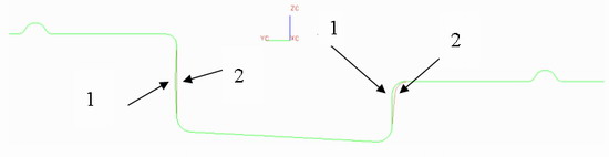

Figure 2 section and negative angle inspection
Second, the overall plan of the profile processing
Third, the specific processing technology of the concave mold NC machining 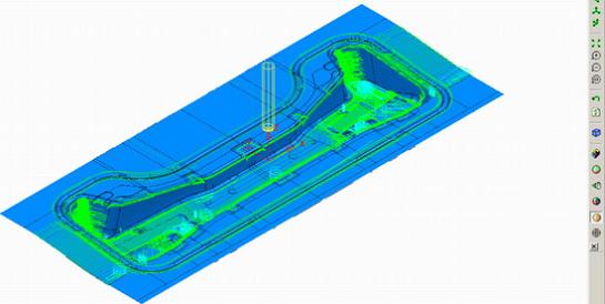
3. Clear root before semi-finishing 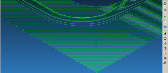
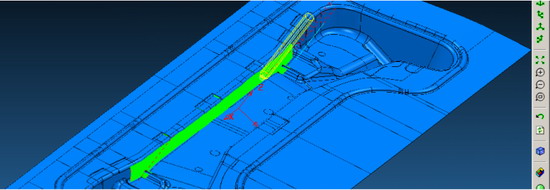
Figure 5: 20° parallel angle, arc connection
Third, the conclusion
The function of the sight glass is to observe the liquid level of the refrigerant and detect the presence of moisture in the back end of the dry filter in the system. In a system with an Expansion Valve, a sight glass is usually fitted in the liquid line immediately after the filter drier. But In theory, the sight glass can be fitted at any desired location on the discharge line. However, placing the sight glass close to the expansion valve is especially advisable.