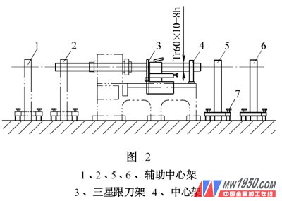
The largest lathe for processing shaft parts in our factory is CW6280×3000, and its maximum processing range is 800 mm×3000 mm. It is now necessary to machine a screw as shown in Figure 1, with a size of 60 mm x 6302 mm, which greatly exceeds the longest processing range of the lathe. Through the analysis of the pattern and on-site inspection, the outer diameter of the screw blank is smaller than the spindle aperture (85mm), and the tooling is improved. The screw can be processed on the CW6280×3000 lathe. The length to diameter ratio of the filament rod is L/d of 105, which must be processed according to the requirements of the slender shaft process. Because of its poor rigidity, bending, vibration and deformation during the cutting process, the tooling and tool geometry are carefully designed and studied. 1. Auxiliary tooling design (1) Transition sleeve: The material of the transition sleeve is quenched to 40 HRC or more with 40Cr, the surface roughness Ra of the outer circle is less than 0.8μm, and the roundness error is within ±0.005 mm to reduce the transition sleeve and support. Star wear. The sleeve has a larger diameter than the outer circumference of the machined part by 10 to 15 mm, and four M6 screws are mounted on both ends for clamping the workpiece blank, so that the transition sleeve and the workpiece rotate simultaneously. Adjust the sleeve axis so that the workpiece axis coincides with the spindle rotation axis (see Figure 3). Next page V Opening Valve Balls,Stainless Three L Port Valve Spheres,Stainless Three T Port Valve Spheres,Stainless V Port Valve Spheres WENZHOU ZHENHONG VALVE BALL CO., LTD , https://www.zhvalveball.com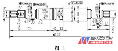
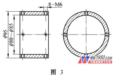
Use one end of a multi-supported screw to clamp the other end with a three-jaw self-centering chuck, and support it with a Samsung tool holder, a center frame, and a transition sleeve. In order to avoid bending deformation caused by self-weight, a plurality of auxiliary center frames are used to support the extra long portion to assist the support to increase the rigidity of the process. The specific clamping is shown in Figure 2.