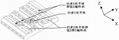
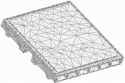
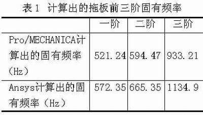
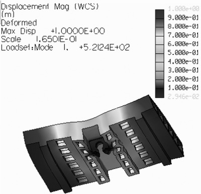
The carriage slides on the guide rail, and the guide rail constrains the movement of the carriage in the Z direction and the rotation around the X and Y axes. The screw seat constrains the translation of the carriage in the Y direction, and the pressure plate between the carriage and the guide rail restricts the translation of the carriage in the X direction and the rotation in the Z direction. In the MEC STRUCT menu, select Constraints→New→Surface, and define the above constraints in the definition dialog box that pops up, as shown in Figure 2. Figure 2 Constraints imposed on the carriage 4. Divide the grid In the MEC SRTUCT menu, select the MESH menu option to define and divide the grid, and check the quality of the mesh. The grid that does not meet the requirements will be displayed in red in the finite element mesh model. The finite element mesh model of the carriage is shown in Figure 3. Figure 3 finite element mesh model of the carriage 5. Establish analytical tasks for finite element calculations Select Analyses/Studies in the MEC STRUCT menu, and select File→New Modal... in the Analyses and Design Studies dialog box that pops up. The modal analysis task definition dialog box pops up, and the analysis task is set in this dialog box. Analysis calculated. Fourth, the machine finite element modal analysis results For the solution of the finite element model of the machine tool, it is generally not necessary to find the full natural frequency and mode shape of the vibration system. Since the low-order mode has a great influence on the vibration system, only the first three modes are calculated. At the same time, in order to verify the correctness of the finite element software Pro/MECHANICA for the modal calculation of the machine tool parts, this paper uses the current popular general finite element analysis software ANSYS to calculate the finite element mode of the machine tool carriage, and calculate the first three orders. The natural frequency and mode shape are compared with the calculation results of Pro/MECHANICA. The pair of natural frequencies is shown in Table 1, and the comparison of the first three modes is shown in Figure 4. a) Pro/ENGINEER first-order mode diagram Previous page next page Sf6 Gas Pressure Gauge,Sf6 Gas Pressure Tester,Sf6 Gas Test Gauge,Sf6 Manometer Gas wuxi kaifeng pressure gauge co., ltd , https://www.wxkfmanometer.com
3. Define constraints