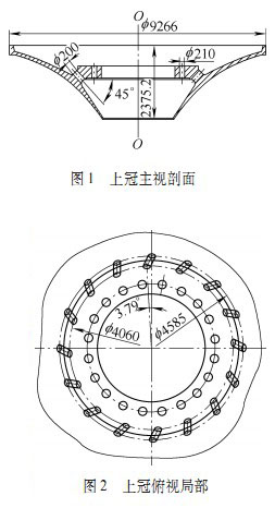
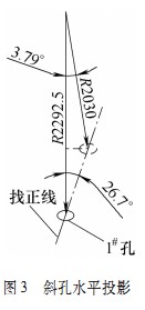
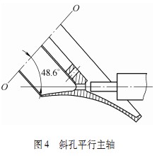
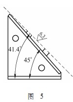
The runner is the motive core component of the turbine. It is assembled and welded by super-large precision parts such as the upper crown, lower ring and blades, and then precision machined. The Three Gorges Runner is the largest runner in the world today. The heaviest component of the runner assembly is crowned, not only with a tonnage of 106.5t, but with a diameter of 9266mm, and its complex structure is a double-cone cavity with an oblique drain hole. Body structure. In the Three Gorges underground power station 2# runner (in-plant number) is the last runner produced by our company for the Three Gorges Power Station. In the production process, because the upper crown is semi-finished, it is not processed completely (the remaining 20 vertical methods) Lankong and 16 oblique drain holes are not processed). Only after the processing of the upper crown is completed, the subsequent welding and overall processing of the upper crown, the blade and the lower ring can be started. Therefore, the processing condition of the upper crown becomes a major bottleneck affecting the manufacturing cycle of the underground 2# runner. 1. Structural features of the crown of the Three Gorges The upper crown is integrally cast with stainless steel material 06Cr13Ni4Mo, the height is 2375.2mm, the maximum diameter is 9266mm, and the finished product weight is 106.5t. As shown in the upper cross-sectional view of Fig. 1, the back of the upper crown is a conical overcurrent surface, the front side is also a conical surface, and the middle is a hollow body structure. On the top view of the crown of Fig. 2, there are 20 φ210mm flange holes and 16 φ200mm drain holes. According to the analysis pattern, 20 φ210mm flange holes perpendicular to the flange surface can be easily machined by using a vertical boring machine or by standing up the workpiece. However, the 16 φ200mm drain holes are deep into the inner cavity in the middle of the super large tapered workpiece. The hole itself has a spatial angle with respect to the workpiece axis, and the diameter is large, the machining distance is long, and the clamping point is small, so the conventional Equipment processing is very difficult. 2. Equipment and tooling The upper crown itself is very heavy, and the size of the hole to be processed is large, and the trampoline capable of processing such an oversized part is rare in China. However, the continued processing of the semi-finished products of the upper crown allows us to use only the TX6925 floor boring and milling machine produced by Wuhan Heavy Machine Tool Plant. Since the device does not have a rotary table, there is no universal feed mechanism. Although the machining capability of the workpiece is "heavy" and "large", the processing of this special oblique drain hole is slightly difficult. ". The equipment parameters of the TX6925 floor boring and milling machine are: 17m horizontal stroke of the trampoline column, 6m vertical stroke of the spindle box, 1.5m of the spindle ram working stroke, and 1.5m of the spindle working stroke. The spindle has a diameter of 250 mm and can only be fed in the axial direction. Since the factory has never processed the oblique hole of the super large tapered part, the processing of the water leakage hole of the crown of the Three Gorges is faced with no special equipment and no special tooling. How to use the common tooling to achieve effective fixing and clamping of the oversized cone with a weight of 106.5t, and the processing of the upper crown oblique hole with conventional equipment has become the core problem of the processing technology of the upper crown. 3. Process analysis and implementation (1) Preliminary analysis It can be seen from Fig. 1 and Fig. 2 that using T6925 boring and milling machine and common tooling to realize the processing of 16 φ200mm oblique drain holes, the following problems should be solved: how to place the workpiece relative to the machine tool; What kind of tooling is used; how to lift the workpiece and adjust the spatial angle of the drain hole; the trampoline does not have a universal feed, and how to turn to the next hole for processing. Since the drain hole has a spatial angle and the machine tool can only feed in a single direction, then to solve the above problem, it is necessary to start from the analysis and calculation of the pattern around the space angle of the drain hole. (2) Calculate the projection of the axis of the drain hole on the vertical section at an angle of 45° to the workpiece axis; on the top view (ie, the horizontal projection surface), the projection pitch of the drain hole inlet is φ4585mm, and the exit projection pitch is Φ4060mm; in the top view (ie horizontal projection surface), the centripetal line of the discharge center of the drain hole exit is at an angle of 3.79° to the centripetal line of the entrance projection center. Using the trigonometric function and the spatial straight line equation, it can be calculated (or simulated by the SolidWorks software, the upper crown entity is measured): on the top view (ie, the horizontal projection surface), taking the ## drain hole as an example, φ200mm draining water The axis projection of the hole inlet center is at an angle of 26.7° to the inlet center of the drain hole (see Fig. 3). The projection line can be used as a alignment line for processing the drain hole later, and the line and the trampoline can be made when the workpiece is found. The horizontal rail is vertical. In the space adjustment workpiece, taking the 1# drain hole as an example, rotate around the workpiece axis O-O, so that the drain hole axis is perpendicular to the trampoline horizontal guide rail (ie, the horizontal projection of the drain hole axis is parallel to the trampoline main sleeve). Keep the workpiece axis perpendicular to the horizontal guide of the trampoline, and then adjust the angle between the workpiece axis O_O and the axis of the trampoline spindle so that the axis of the drain hole is parallel to the axis of the spindle. At this time, the workpiece axis O_O is at an angle of 48.6° with the spindle of the boring machine (see Fig. 4). Through the above pattern analysis and calculation, we can see that for each drain hole, we only need to find the workpiece according to the alignment line shown in Figure 3 and the angle shown in Figure 4, and adjust the drain hole on the workpiece to Parallel draining holes can be machined in parallel with the spindle of the boring machine and then effectively clamping the workpiece on the tooling. (3) Process design Using the common tooling and tools in the workshop, the following process scheme is formed for the processing of the drain hole: 20 φ210mm flange hole processing lines and 16 φ200mm drain hole processing lines are made, and the sample is used (using galvanizing) The board is cut and made), and the projection line of the drain hole axis on the flange surface (ie, the projection on the top view) is made, as shown in Fig. 3; processed by a vertical boring machine (model WHZ-067 Wuhu Machine Tool Factory) 20 φ210mm flange holes (can also be placed on the workpiece, the flange surface is vertically boring); use conventional large-piece hoisting to hang in the four flange holes corresponding to the 1# drain hole Workpiece; drop the workpiece onto the designed tooling assembly, fine-tune the workpiece according to the 26.7° projection line and the 48.6° workpiece axis space angle, so that the 1# drain hole axis is parallel to the 镗 axis; correct the workpiece, drill, 镗1# drain hole to pattern requirements; change the lifting hole, re-adjust the workpiece, and process the remaining drain holes in sequence. Color Eva Film,Eva Adhesive Film,Color Eva Films,Color Movie Film HUAKAI FENGSHI TECHNOLOGY (CHONGQING) CO., LTD. , https://www.cqhkpvb.com